A digital multimeter abbreviated as DMM by most industry players is a standard test tool used to take electric measurements for more than one electric component. Most basic digital multimeters are used by technicians to gauge voltage, resistance and current for diagnostic purposes. A DMM is assembled by combining a microprocessor control and an input keyboard.Keyboards include features such as switches that allow users to select the parameters they prefer accessing.
Microprocessors, on the other hand, control the display of parameters that are accessed via internal meters connected to the device. According to the authors of ‘Digital Multimeter with Microprocessor Control.” U.S. Patent No. 5,396,168. 7’ the keyboard takes instructive signals from the microprocessor and sublimes to control where its resistor and switch interconnect and configure the device to access selected parameters within determined ranges. DMMs had to be invented to replace the previous inferior analogue meters which had a much-diminished rate of accuracy and reliability. DMMs also had the advantage of increased impedance compared to their earlier analogue forms. Digital multimeters combined some functions performed by several different needle-based analogue meters such as the ammeter, the ohmmeter and the voltmeter.
The Analogue Tools That Got Compressed into Digital Multimeter Devices
-
- The Ohmmeter that used to measure resistance in ohms
- The voltmeter that used to measure volts
- The ammeter that used to measure current in amperes (amps)
Since different electricians and technicians have different job descriptions all working with some similar electric parameters but some others more specialised, not all digital multimeters are similar. Apart from the usual basic parameters scaled and measured, some specialised digital multimeters incorporate specialised features and more advanced options. Others may have the same parameter features but specialised to measure very large amounts of the same parameters or very minute features as well. Therefore, overload functions must be very well calculated to suit the different electrical ranges that may be called for by these devices. Depending on the needs of a technician, customisation has been done to conjure very different kinds of the same family of electrical measurement devices.
The basic parameters that digital multimeters assess when troubleshooting devices and their circuits
- Voltage
- Current
- Resistance
- Continuity- Continuity tests determine whether two terminals or objects are electrically connected.
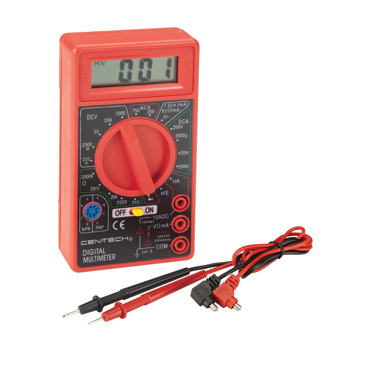
Basic Components of a Simple-Faced Digital Multimeter
-
- The display allows users to read out the measurements of parameters gauged
- Buttons function to allow users to select parameter and range options
- The dial or rotary switch allows users to select measurements and to reset them to their default or zero error levels.
- Input jacks are allocations for inserting test leads.
Test leads should be flexible and insulated. These wires (test leads) are always in pairs. Red leads are for positive terminal, and black ones are meant for negative terminals. They get plugged into this measuring devices to conduct energy from the item which is being diagnosed by the user. On each test lead, probe tips are specifically placed to touch and join circuits and access them.
Types of Probes
-
- Alligator Clips are great cables instrumental in joining with large wires and useful for tests that could take long enough to warrant testers to desire to let go of the probes
- Tweezers are useful especially when testing SMD components
- IC hooks are needed most when testing minute ICs
- Test probes are cheap and are mostly used as replacements